- 您现在的位置:买卖IC网 > Sheet目录138 > NSR0240V2T1G (ON Semiconductor)DIODE SCHOTTKY 40V 250MA SOD523
发布紧急采购,3分钟左右您将得到回复。
     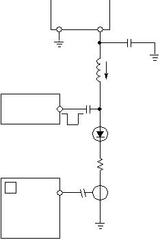 NSR0240V2T1G, NSVR0240V2T1G http://onsemi.com 2 THERMAL CHARACTERISTICS Characteristic Symbol Max Unit Thermal Resistance Junction?to?Ambient (Note 1) Total Power Dissipation @ TA = 25 ?C R P JA D 600 200 ?C/W mW Thermal Resistance Junction?to?Ambient (Note 2) Total Power Dissipation @ TA = 25 ?C R P JA D 300 400 ?C/W mW Junction and Storage Temperature Range TJ, Tstg ?55 to +150 ?C 1. Mounted onto a 4 in square FR?4 board 10 mm sq. 1 oz. Cu 0.06” thick single?sided. Operating to steady state. 2. Mounted onto a 4 in square FR?4 board 1 in sq. 1 oz. Cu 0.06” thick single?sided. Operating to steady state. ELECTRICAL CHARACTERISTICS (TA = 25 ?C unless otherwise noted) Characteristic Symbol Min Typ Max Unit Reverse Leakage (VR = 10 V) (VR = 25 V) (VR = 40 V) IR ? ? ? ? 0.2 0.5 0.55 2.0 10 A Forward Voltage (IF = 10 mA) (IF = 100 mA) (IF = 200 mA) VF ? ? ? 345 485 580 390 550 700 mV Total Capacitance (VR = 5.0 V, f = 1 MHz) CT ? 4.0 ? pF Reverse Recovery Time (IF = I R = 10 mA, I R = 1.0 mA) trr ? 3.0 ? ns 1. DC Current Source is adjusted for a Forward Current (IF) of 10 mA. 2. Pulse Generator Output is adjusted for a Peak Reverse Recovery Current IRM of 10 mA. 3. Pulse Generator transition time << trr. 4. IR(REC) is measured at 1 mA. Typically 0.1 X I RM or 0.25 X I RM. 5. tp ? t rr RL = 50 Current Transformer DUT 750 H 0.1 F 50 Output Pulse Generator tr tp 10% 90% IF IRM trr iR(REC) = 1 mA Output Pulse (IF = I RM = 10 mA; measured at iR(REC) = 1 mA) IF Pulse Generator Output Figure 1. Recovery Time Equivalent Test Circuit 50 Input Oscilloscope 0.1 F 0 V VR DC Current + Source Adjust for IRM ? |
| *型号 | *数量 | 厂商 | 批号 | 封装 |
|---|---|---|---|---|
|
|
添加更多采购
